Table of Contents
Introduction
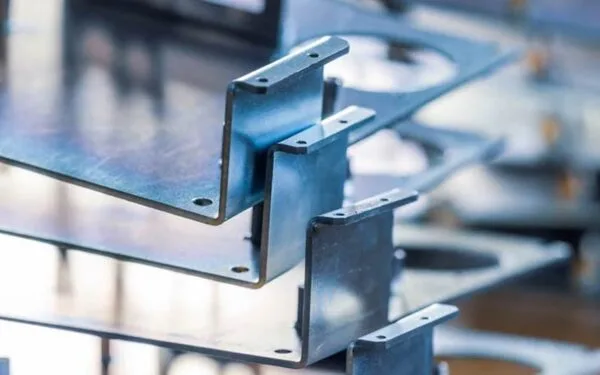
The quality of a fabricated metal component is rarely determined by a single manufacturing operation. In most industrial projects, the finished part is the result of a carefully controlled sequence involving engineering review, material selection, cutting, forming, joining, surface treatment, and inspection. Understanding this complete sheet metal fabrication process is therefore important for engineers, sourcing teams, OEM manufacturers, and companies developing custom metal products.
Sheet metal fabrication is widely used to manufacture enclosures, brackets, machine frames, panels, housings, cabinets, guards, structural components, and numerous customized industrial parts. The process can support everything from prototype development to repeatable production, but successful results depend on choosing the right combination of materials, equipment, tolerances, forming methods, and quality-control procedures.
For industrial customers, the real question is not simply whether a factory can cut and bend sheet metal. A capable manufacturing partner must understand how every production stage influences dimensional accuracy, structural strength, assembly compatibility, surface quality, and long-term product performance.
Linametalworks provides precision machining and custom metal fabrication support for industrial projects requiring customized components, combining multiple metalworking processes according to the requirements of each part.
What Is the Sheet Metal Fabrication Process?
The sheet metal fabrication process is a series of manufacturing operations used to transform flat metal sheets into functional components or assemblies.
Depending on the product, the process may include cutting, punching, bending, forming, machining, welding, fastening, grinding, finishing, and inspection. Some relatively simple components may require only cutting and bending, while complicated industrial assemblies can pass through several manufacturing departments before completion.
A typical workflow can be summarized as:
- Engineering drawing and design review
- Material selection
- Sheet preparation
- Cutting or punching
- Bending and forming
- Machining or secondary processing
- Welding and assembly
- Surface treatment
- Dimensional inspection
- Final assembly and quality verification
Although this sequence appears straightforward, each stage is closely connected with the next. Poor cutting accuracy can cause bending problems. Incorrect bend allowances may result in assembly misalignment. Excessive welding heat can distort an otherwise accurate part. Surface treatments can also influence dimensional features if coating thickness is not considered during design.
For this reason, professional sheet metal fabrication should be viewed as an integrated manufacturing system rather than a collection of independent operations.
Stage 1: Engineering Review and Design for Manufacturing
Every successful sheet metal project begins before any metal reaches a cutting machine.
Manufacturers first review engineering drawings, CAD models, dimensional specifications, material requirements, tolerance information, welding symbols, surface treatment instructions, and expected operating conditions.
This stage is commonly associated with Design for Manufacturing, or DFM. The objective is to determine whether a component can be produced efficiently and consistently using the intended fabrication methods.
Engineers may evaluate issues such as:
- Material thickness
- Minimum bend radius
- Hole-to-edge distance
- Hole-to-bend distance
- Bend direction
- Internal corner geometry
- Welding access
- Assembly clearances
- Fastener positions
- Surface finishing requirements
Good DFM analysis does not mean changing the purpose of the component. Instead, it seeks to maintain the required performance while reducing unnecessary manufacturing difficulty.
For example, placing a hole extremely close to a bend may cause deformation during forming. A design may therefore need to modify the hole position or manufacturing sequence to maintain dimensional accuracy.
Similarly, unnecessarily tight tolerances across every feature can make production more difficult without improving actual product performance. Critical dimensions should receive appropriate controls, while non-critical features can use practical general tolerances.
This design-stage collaboration is especially important for customized industrial components because many parts must interact with existing machinery, electrical equipment, frames, fasteners, or other assemblies.
Stage 2: Selecting the Right Sheet Metal Material
Material selection directly influences nearly every subsequent fabrication operation.
Different metals respond differently to cutting, bending, welding, machining, and finishing. The best material therefore depends on mechanical requirements as well as the intended manufacturing route.
Common materials used in sheet metal fabrication include:
| Material | Main Characteristics | Typical Applications |
|---|---|---|
| Carbon Steel | Strong, versatile and widely fabricated | Frames, brackets, machinery components |
| Stainless Steel | Corrosion resistant and durable | Equipment housings, food or industrial components |
| Aluminum | Lightweight and corrosion resistant | Enclosures, panels, transportation components |
| Galvanized Steel | Protective zinc-coated surface | Cabinets, structural and outdoor components |
| Copper | High electrical and thermal conductivity | Electrical and thermal components |
| Brass | Good machinability and corrosion resistance | Decorative and precision components |
Material specifications should not be treated casually. Differences in alloy composition, temper, thickness, and mechanical properties can change how a sheet behaves during bending or welding.
Engineering teams commonly refer to standardized material specifications during material selection. ASTM International publishes widely used standards covering metallic materials, testing procedures, mechanical properties, and numerous manufacturing-related requirements.
For buyers, providing the correct material specification at the beginning of a project can prevent significant misunderstandings later in production.
Stage 3: Cutting the Sheet Metal
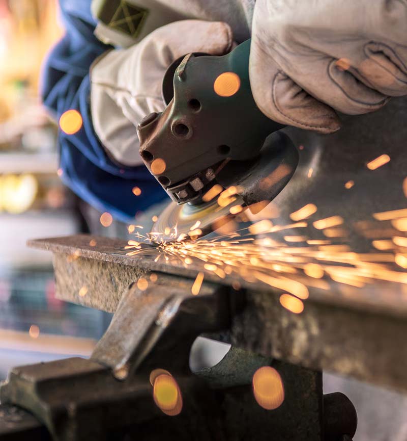
Once the design and material have been confirmed, the flat sheet must be cut into the required profile.
Modern fabrication facilities may use several cutting technologies depending on material type, thickness, geometry, edge-quality requirements, and production volume.
Laser Cutting
Laser cutting is widely used for producing complex profiles, holes, slots, and detailed features with high accuracy.
Its advantages include good edge quality, high flexibility, and the ability to switch between different part designs without dedicated tooling.
Laser cutting is particularly useful for customized sheet metal components because digital files can be converted directly into cutting programs.
CNC Punching
CNC punching uses tooling to create holes, slots, cutouts, and formed features.
It can be highly efficient when parts contain repeated geometric features. Depending on equipment capability, punching systems may also create louvers, countersinks, and other formed details.
Sawing and Mechanical Cutting
Mechanical cutting methods remain useful for certain materials, straightforward profiles, structural components, or pre-processing operations.
The correct cutting method should be chosen according to the component rather than assuming one technology is universally superior.
Cutting accuracy matters because every following manufacturing operation starts with the blank produced during this stage. Incorrect dimensions at the cutting stage can accumulate into larger assembly errors after bending and welding.
Stage 4: Sheet Metal Bending and Forming
After cutting, many sheet metal parts must be bent into three-dimensional shapes.
Bending appears simple, but accurate forming requires careful consideration of material behavior.
When metal bends, material on the outside of the bend stretches while material on the inside compresses. The neutral region between these areas influences the final developed length of the flat sheet.
Manufacturers therefore need to account for:
- Bend allowance
- Bend deduction
- Material thickness
- Bend radius
- Tool geometry
- Material springback
Springback occurs when the material partially returns toward its original shape after forming pressure is removed. Different alloys and thicknesses exhibit different amounts of springback, which must be compensated for during production.
For precision components, bending sequence is also important. A poorly planned sequence can make later bends impossible to access or can cause interference between the part and tooling.
Complex sheet metal assemblies therefore benefit from early collaboration between engineering and manufacturing teams.
Why Bend Radius Matters
The bend radius affects both manufacturing feasibility and part strength.
If the inside bend radius is too small for the selected material and thickness, the metal may crack or weaken near the bend. Excessively large radii, however, may interfere with assembly geometry.
Designers should therefore avoid choosing bend radii purely for appearance. They should consider material properties, tooling capability, structural requirements, and available production methods.
This is an example of why a complete sheet metal fabrication process requires coordination between design and production rather than simply following a drawing without manufacturing review.
Stage 5: Secondary Machining and Precision Features
Not every required feature can be efficiently produced directly during laser cutting or forming.
Some fabricated components also require secondary machining operations such as:
- CNC milling
- Drilling
- Tapping
- Counterboring
- Countersinking
- Reaming
- Precision hole finishing
These operations become especially important when fabricated parts must connect with precision-machined components or when assembly features require tighter tolerances than standard sheet fabrication can provide.
Combining fabrication and machining capabilities can simplify the supply chain for industrial projects because the manufacturer can control multiple operations within one production workflow.
For projects involving both fabricated and machined components, Linametalworks’ precision manufacturing capabilities can support integrated custom metalworking requirements rather than treating machining and fabrication as completely separate processes.
Stage 6: Welding and Metal Assembly
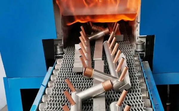
After cutting and forming, individual sheet metal components may need to be joined into larger structures.
Welding is one of the most common joining methods used in metal fabrication. Depending on the material, component design, and application, manufacturers may use processes such as MIG welding, TIG welding, resistance welding, or other specialized joining methods.
The appropriate process depends on factors including:
- Material type
- Sheet thickness
- Required joint strength
- Appearance requirements
- Production volume
- Heat sensitivity
- Accessibility of the weld joint
Welding quality involves more than producing a strong joint.
Heat introduced during welding can cause distortion, especially in thin sheet metal. If deformation is not controlled, mounting surfaces, holes, doors, panels, or other features may move outside required dimensional limits.
Manufacturers can reduce distortion by controlling welding sequence, fixturing, heat input, joint design, and cooling conditions.
This makes fixture design particularly important for welded assemblies. A good fixture helps maintain component position while allowing the welder or automated equipment to access the required joints.
For general manufacturing technology and advanced production systems, the U.S. National Institute of Standards and Technology maintains extensive manufacturing research and resources covering modern manufacturing technologies, measurement, standards, and production innovation.
Stage 7: Grinding, Deburring and Edge Preparation
Cutting, drilling, machining, and welding can leave sharp edges, burrs, weld beads, or surface irregularities.
These features may affect safety, assembly, coating adhesion, or product appearance.
Deburring and finishing operations can include:
- Edge rounding
- Grinding
- Sanding
- Weld smoothing
- Surface blending
- Polishing
Not every component requires a cosmetic finish. Industrial brackets hidden inside equipment may require only functional edge treatment, while visible enclosures may need significantly more surface preparation.
Defining the required finishing level on the drawing helps prevent ambiguity.
This is particularly relevant for B2B projects because different interpretations of terms such as “smooth,” “polished,” or “finished” can lead to inconsistent expectations unless technical requirements are clearly specified.
Stage 8: Surface Treatment and Corrosion Protection
Surface treatment can improve corrosion resistance, wear resistance, appearance, electrical properties, or environmental durability.
Common finishing methods for fabricated components include:
- Powder coating
- Painting
- Anodizing
- Plating
- Passivation
- Polishing
- Brushing
The correct finish depends on both material and application.
For example, aluminum components may be anodized when additional surface protection or appearance control is required, while carbon-steel structures may receive powder coating or another protective treatment.
Surface finishing needs to be considered during design because coatings can influence dimensions.
Threaded areas, grounding surfaces, mating faces, precision holes, and electrical contact locations may need masking or special treatment.
A supplier that understands both fabrication and finishing requirements can identify these issues before they become assembly problems.
Stage 9: Dimensional Inspection and Quality Control
Inspection should occur throughout production rather than only after the part has been completely fabricated.
A complete quality-control workflow may include incoming material verification, first-piece inspection, in-process dimensional checks, welding inspection, final dimensional verification, and surface-quality evaluation.
Important features may be inspected using:
- Calipers
- Micrometers
- Height gauges
- Thread gauges
- Coordinate measuring equipment
- Welding inspection tools
- Surface measurement instruments
The appropriate inspection method depends on tolerance and component complexity.
Quality systems based on internationally recognized frameworks can also help manufacturers standardize production and documentation. ISO 9001 quality management principles focus on controlled processes, customer requirements, risk-based thinking, performance evaluation, and continual improvement.
For sourcing teams, this matters because consistent manufacturing is more important than producing one successful sample. The objective is for later batches to remain within the same defined requirements.
Critical Quality Factors Throughout Fabrication
Several areas deserve particular attention when evaluating fabricated metal components.
| Quality Factor | Why It Matters |
|---|---|
| Material Verification | Confirms the specified material is used |
| Cutting Accuracy | Establishes the geometry for later processes |
| Bend Accuracy | Determines final dimensions and assembly fit |
| Hole Position | Affects mounting and component alignment |
| Weld Quality | Influences structural strength and distortion |
| Surface Condition | Affects appearance and coating performance |
| Dimensional Inspection | Confirms compliance with drawings |
| Process Documentation | Supports production consistency |
A strong quality strategy prioritizes dimensions and features according to functional importance instead of treating every characteristic identically.
Sheet Metal Fabrication vs CNC Machining
Sheet metal fabrication and CNC machining are frequently used together, but they serve different manufacturing requirements.
CNC machining removes material from a solid workpiece, while sheet metal fabrication transforms relatively thin metal sheets through cutting, bending, joining, and related processes.
| Factor | Sheet Metal Fabrication | CNC Machining |
|---|---|---|
| Starting Material | Flat metal sheet | Solid block, bar or billet |
| Main Operations | Cutting, bending, welding | Milling, turning, drilling |
| Typical Products | Enclosures, frames, panels | Precision mechanical parts |
| Material Efficiency | Often high for thin structures | More material removed |
| Complex Internal Features | More limited | Strong capability |
| Large Hollow Structures | Highly suitable | Often inefficient |
Neither method is inherently better. The correct process depends on product geometry and functional requirements.
For example, an industrial control enclosure may use fabricated sheet metal for the housing while requiring CNC-machined mounting components, shafts, fittings, or interfaces.
Manufacturers capable of combining these processes can support more complete assemblies.
Sheet Metal Fabrication vs Metal Stamping
Fabrication and stamping also overlap but are normally selected for different production scenarios.
Sheet metal fabrication is highly flexible and works well for prototypes, customized designs, engineering changes, and many industrial production quantities.
Metal stamping uses dedicated tooling to form components and can become highly efficient when the same part is produced repeatedly at significant volume.
Fabrication may therefore be more appropriate when:
- Product designs change regularly
- Multiple variants are required
- Dedicated tooling is unnecessary
- Components are relatively large
- Welding or assembly is involved
Stamping may be more appropriate when:
- Production quantities are high
- Geometry is stable
- Repeatability is critical
- Dedicated tooling is justified
In some projects, both methods may be used within the same assembly.
How Sheet Metal Fabrication Supports Industrial Enclosures
One of the most important applications of sheet metal fabrication is industrial enclosure manufacturing.
Electrical equipment, automation systems, network infrastructure, industrial controls, and machinery often require protective housings.
A fabricated enclosure may contain:
- Panels
- Doors
- Mounting plates
- Hinges
- Ventilation openings
- Cable entry points
- Brackets
- Fastener systems
Each of these features affects manufacturability.
For example, doors need adequate clearance after coating. Mounting holes must align with internal components. Ventilation patterns should maintain sufficient sheet strength. Grounding areas may need special surface treatment requirements.
This illustrates why industrial enclosure fabrication requires more than basic bending capability. Successful production depends on understanding the complete assembly.
Prototype Fabrication and Production Fabrication
Prototype and production fabrication share similar manufacturing processes but have different priorities.
During prototype development, engineering flexibility is often most important. Designers may need to test fit, evaluate assembly behavior, change dimensions, or modify mounting features.
Digital cutting and CNC bending make these revisions relatively straightforward because new components can often be manufactured without creating completely new dedicated tooling.
During repeat production, priorities shift toward process consistency, fixture control, standardized inspection, predictable cycle times, and repeatable surface quality.
Manufacturing partners that understand both phases can help companies transition more smoothly from initial development to stable production.
Common Sheet Metal Fabrication Problems
Understanding typical problems helps engineering and sourcing teams identify manufacturers with appropriate process control.
Dimensional Variation After Bending
Possible causes include material variation, springback, tooling conditions, and incorrect bend compensation.
Welding Distortion
Excessive heat or poor welding sequence can deform thin metal assemblies.
Misaligned Holes
Hole positions can shift when bend allowances or forming sequences are not correctly considered.
Poor Surface Finish
Scratches, inconsistent grinding, contamination, or insufficient surface preparation can become visible after coating.
Assembly Interference
Parts may be individually within tolerance but still fail to assemble properly when tolerance accumulation has not been considered.
The most effective approach is preventing these issues through engineering review and process planning rather than attempting to correct every problem during final inspection.
How to Choose a Sheet Metal Fabrication Partner
Industrial buyers should evaluate more than the size of a fabrication facility.
A suitable supplier should understand the complete relationship between design, materials, production, inspection, and final application.
Key areas to evaluate include manufacturing capability, engineering support, quality systems, material experience, equipment, communication, documentation, and ability to coordinate secondary processes.
It is also valuable to determine whether the supplier can support multiple manufacturing technologies. A project that includes fabricated frames, CNC-machined interfaces, welded assemblies, and finished metal components can become difficult to manage when each operation is handled by an unrelated supplier.
An integrated manufacturer can reduce handoffs and improve communication across processes.
When evaluating custom metal manufacturing support from Linametalworks, engineering teams can consider the complete requirements of the component rather than viewing cutting, bending, machining, and fabrication as isolated operations.
What Information Should You Provide for a Fabrication Project?
Providing complete technical information improves communication and helps manufacturers evaluate projects accurately.
Useful information normally includes:
- 2D engineering drawings
- 3D CAD files
- Material specification
- Sheet thickness
- Critical tolerances
- Welding requirements
- Surface finish
- Assembly requirements
- Required quantity
- Functional application information
It is particularly important to identify critical dimensions rather than simply applying tight tolerances to every feature.
For assemblies, exploded drawings or interface information can also help manufacturers understand how individual parts fit together.
Good project information allows engineering teams to identify potential fabrication issues before production begins.
Future Trends in Sheet Metal Fabrication
Modern fabrication is becoming increasingly digital and integrated.
CAD/CAM systems, automated cutting, CNC bending, robotic welding, digital inspection, production tracking, and manufacturing data systems are helping manufacturers improve repeatability and process visibility.
Automation does not eliminate the importance of manufacturing expertise. Instead, it increases the value of engineers who understand how to convert product requirements into stable processes.
Future competitiveness in sheet metal fabrication is therefore likely to depend on combining equipment capability with engineering knowledge, quality management, flexible manufacturing, and reliable production data.
For industrial buyers, this means supplier evaluation should increasingly consider process integration rather than simply comparing individual machines.
Conclusion
The sheet metal fabrication process is a coordinated manufacturing workflow that transforms flat metal material into functional industrial components through engineering review, cutting, bending, machining, welding, finishing, and quality inspection.
Each stage influences the next. Material choice affects bending. Cutting accuracy affects assembly. Welding influences dimensional stability. Surface treatment affects appearance and mating features. Quality inspection confirms whether all of these operations have produced the intended result.
For OEMs, equipment manufacturers, engineering teams, and industrial sourcing professionals, selecting a fabrication partner should therefore involve more than identifying a company that owns cutting and bending equipment. Engineering support, material knowledge, process integration, quality control, and the ability to manage multiple manufacturing operations are equally important.
Linametalworks supports customized metalworking projects through precision manufacturing and fabrication capabilities. Companies developing fabricated structures, precision components, or integrated metal assemblies can learn more about Linametalworks’ custom manufacturing capabilities.
Frequently Asked Questions
What is the sheet metal fabrication process?
The sheet metal fabrication process converts flat metal sheets into finished components through operations such as cutting, bending, machining, welding, finishing, and inspection. The exact sequence depends on the design and application.
What materials are commonly used in sheet metal fabrication?
Common materials include carbon steel, stainless steel, aluminum, galvanized steel, copper, and brass. Material selection depends on strength, corrosion resistance, weight, forming characteristics, welding compatibility, and operating environment.
What is the difference between sheet metal fabrication and CNC machining?
Sheet metal fabrication generally forms relatively thin metal sheets through cutting, bending, and joining, whereas CNC machining removes material from solid workpieces to create precision components. Many industrial assemblies use both processes.
Why is DFM important in sheet metal fabrication?
Design for Manufacturing helps identify potential problems involving bend radius, hole location, tolerances, welding access, assembly clearance, and material behavior before production begins. This can improve consistency and reduce unnecessary manufacturing complexity.
How can sheet metal fabrication quality be controlled?
Quality can be controlled through material verification, first-piece inspection, in-process dimensional measurement, bend and weld control, final inspection, standardized documentation, and well-defined engineering requirements.