Table of Contents
Introduction
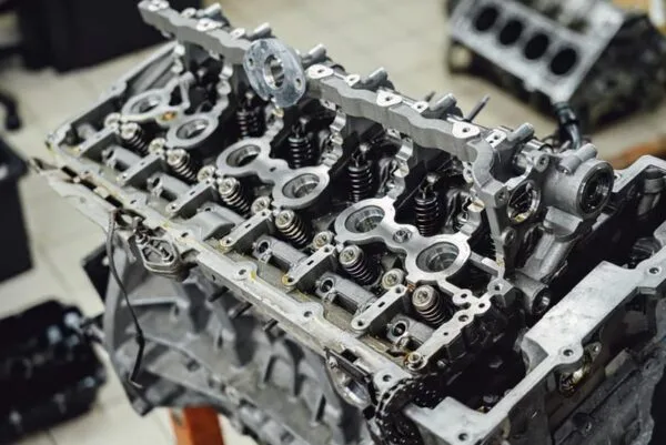
Automotive manufacturing depends on thousands of metal components that must fit together accurately, withstand vibration and mechanical loads, and remain consistent across large production quantities. Brackets, reinforcements, clips, covers, mounting plates, structural elements, electrical components, and numerous supporting parts are commonly manufactured through automotive metal stamping.
Metal stamping is particularly valuable in automotive production because it can transform sheet or coil material into repeatable components through cutting, punching, bending, drawing, and forming operations. Once the tooling and production process have been validated, large quantities of parts can be manufactured with stable geometry and relatively short cycle times.
However, successful automotive stamping involves much more than press capacity. Material properties, die engineering, lubrication, strip layout, feeder accuracy, springback, tooling wear, dimensional inspection, production documentation, and secondary processes all influence the final component.
For OEM and Tier suppliers, the objective is not simply to produce a stamped shape. The process must repeatedly deliver components that can move through welding, fastening, coating, assembly, and final vehicle production without creating downstream problems.
Linametalworks provides custom metal stamping services together with bending, CNC machining, casting, forging, and brazing capabilities for OEM and industrial component manufacturing.
What Is Automotive Metal Stamping?
Automotive metal stamping is the use of stamping presses, engineered dies, and controlled material-feeding systems to convert sheet or coil metal into components used in vehicles and related equipment.
A stamping operation may perform one or several manufacturing functions, including blanking, piercing, bending, flanging, drawing, embossing, trimming, and forming.
A relatively simple mounting bracket might begin as a blank cut from coil material before holes are punched and two flanges are formed. A more complicated automotive component may move through several progressive die stations where each press stroke completes another feature.
Common stamped automotive components can include brackets, reinforcement parts, clips, retainers, mounting structures, covers, shields, electrical terminals, chassis-related components, seat-system parts, and equipment supports.
The suitability of stamping depends on part geometry, sheet thickness, material grade, dimensional requirements, and production volume.
Why Metal Stamping Is Important in Automotive Manufacturing
Automotive production places strong emphasis on repeatability.
A part does not only need to meet specifications once. It may need to maintain acceptable dimensions across thousands or millions of production cycles.
This is where properly engineered stamping processes become valuable.
Once a die has been validated and the process stabilized, stamping can provide repeatable positioning of holes, bends, flanges, tabs, and other features.
This consistency affects more than the stamped component itself. It influences downstream operations such as robotic welding, fixture loading, fastening, painting, and final assembly.
A locating hole that gradually shifts because of tool wear, for example, may eventually create alignment problems in a welding fixture. A flange with excessive springback can interfere with mating components even if the blank dimensions were correct.
Automotive metal stamping therefore needs to be understood as part of the complete production system.
Automotive Metal Stamping Process
A typical automotive metal stamping process begins long before the press starts running.
Engineering teams first review the component drawing, material specification, intended production quantity, tolerance requirements, surface condition, and assembly interfaces.
The process normally moves through:
- Component design review
- Material selection
- DFM analysis
- Strip and blank layout
- Die design
- Tool manufacturing and validation
- Material feeding
- Stamping and forming
- In-process inspection
- Secondary manufacturing
- Surface treatment
- Final inspection
The exact sequence varies according to component complexity.
The important principle is that these stages are connected. Material variation can influence forming. Forming can influence hole position. Tool wear can influence burr height. Surface treatment can influence mating dimensions.
Stable automotive production therefore requires control across the entire workflow.
Design for Manufacturing in Automotive Stamping
Design for Manufacturing, or DFM, helps engineering teams identify potential production problems before tooling is completed.
A stamping supplier may review factors such as material thickness, bend radius, hole spacing, flange geometry, forming depth, edge distance, draw ratio, grain direction, and access for later operations.
This stage is particularly important because tooling changes after die completion can become significantly more complicated than changes made during digital design.
For example, a hole located too close to a bend may distort during forming. A narrow section may tear under drawing strain. A flange may interfere with another die station. A component may also be easy to stamp but difficult to inspect or fixture during downstream welding.
Automotive stamping design should therefore consider not only how the part leaves the die but also how it will function in the complete assembly.
Materials Used for Automotive Metal Stamping
Automotive engineers use several metal families depending on strength, weight, corrosion resistance, formability, and component function.
| Material | Important Characteristics | Typical Automotive Uses |
|---|---|---|
| Low-Carbon Steel | Good formability and economical production | Brackets, panels, general structures |
| High-Strength Steel | Increased strength with reduced thickness potential | Structural and reinforcement parts |
| Stainless Steel | Corrosion and heat resistance | Exhaust, brackets, specialized components |
| Aluminum | Lightweight and corrosion resistant | Lightweight panels and structures |
| Copper Alloys | High electrical conductivity | Electrical terminals and contacts |
The exact material grade matters considerably.
Two steels with similar thickness can exhibit very different yield strength, elongation, springback, and forming behavior.
Automotive manufacturers increasingly use advanced and high-strength materials as part of lightweighting strategies. NIST has also highlighted the manufacturing challenge created by increased use of high-strength steels, aluminum, magnesium, titanium, and mixed-material structures in transportation manufacturing, because many of these materials require more advanced forming and joining strategies. NIST’s advanced joining and forming technology research provides additional context on this manufacturing trend.
High-Strength Steel and Stamping Challenges

Higher-strength materials allow engineers to achieve strong structures while potentially reducing material thickness, but they create new forming challenges.
Compared with conventional mild steel, high-strength steels may exhibit greater springback and require higher forming forces.
Stamping engineers therefore need to consider die geometry, press capacity, lubrication, bend radius, and forming sequence carefully.
Springback becomes particularly important.
When the forming load is removed, the material partially recovers toward its original geometry. If the tooling does not compensate for this behavior, the final angle or profile can move outside the required tolerance.
Tool wear may also increase when stronger materials are processed repeatedly.
Automotive stamping processes therefore need to be developed around the actual material grade rather than assuming that identical tooling parameters can be used for every steel sheet.
Aluminum Automotive Stamping
Aluminum is used in automotive applications where weight reduction and corrosion resistance are important.
Compared with conventional automotive steels, aluminum presents different forming characteristics.
Important factors include alloy grade, temper, surface condition, elongation, and bend radius.
Certain aluminum alloys can be formed effectively, while others may be more sensitive to cracking during severe deformation.
Surface handling can also be important because cosmetic automotive components may require careful protection against scratches and die marks.
Automotive manufacturers considering aluminum should therefore evaluate forming behavior at the same time as weight and mechanical performance.
Blanking and Piercing
Blanking establishes the primary external shape of a stamped component.
Piercing creates holes, slots, or internal openings.
Both processes depend strongly on punch-to-die clearance.
If clearance is unsuitable, the process can produce excessive burrs, poor edge geometry, tool wear, or dimensional variation.
In automotive assemblies, holes often serve important locating functions.
A mounting hole may determine the final location of a bracket in an assembly fixture. This means its positional consistency may be more important than the visual appearance of the component.
Tooling and inspection strategies should therefore focus on functional characteristics.
Bending and Flanging
Many automotive stamping parts contain bends and flanges used for reinforcement, mounting, joining, or assembly.
Bending performance depends on material strength, thickness, tooling radius, forming method, and grain orientation.
Flanges can also contribute significantly to structural stiffness.
However, incorrect forming can create cracks, distortion, or inconsistent geometry.
Engineers must also consider how a flange interacts with later manufacturing stages.
For example, a flange used for spot welding needs suitable accessibility and dimensional stability. A flange used as a mounting surface may require tighter positional control.
The stamping drawing should therefore reflect the functional purpose of the formed feature.
Deep Drawing for Automotive Components
Deep drawing converts flat sheet into a deeper three-dimensional geometry.
During drawing, sheet material flows into a die cavity while being controlled by the punch, die, and blank holder.
Automotive applications can include housings, structural shells, covers, and other formed components.
Successful drawing depends on several interacting variables:
- Material ductility
- Blank geometry
- Draw depth
- Punch radius
- Die radius
- Lubrication
- Blank-holder force
If material flow is excessive, wrinkling can occur. If flow is overly restricted, the sheet may tear.
Complex parts may require several drawing stages rather than one severe forming operation.
Progressive Die Stamping
Progressive dies are widely used for relatively small or medium-sized components requiring several repeat operations.
Coil material moves through multiple die stations while remaining connected to a carrier strip.
Different stations may perform piercing, trimming, bending, forming, and final separation.
A simplified production sequence could be:
Feed → Pilot → Pierce → Trim → Form → Bend → Cutoff
The advantage is that multiple manufacturing operations can be incorporated into a highly repeatable cycle.
However, progressive die performance depends heavily on accurate strip feeding.
If the material advances incorrectly, features created at different stations can become misaligned.
Transfer Stamping
Transfer stamping provides another production method for multi-stage components.
Instead of remaining connected to a continuous carrier strip, individual blanks or partially formed parts are transferred between die stations.
Transfer systems can be particularly useful for components requiring deeper forming or larger individual blanks.
Automated transfer systems may move components using mechanical fingers, robotic systems, or specialized transfer mechanisms.
The choice between progressive and transfer stamping depends on component geometry, size, material flow, production volume, and tooling strategy.
Automated Feeding and Press-Line Control
Modern automotive metal stamping increasingly depends on automated material handling.
A production line may combine:
- Decoiling
- Straightening
- Servo feeding
- Punching
- Forming
- Cutting
- Part transfer
- Automated unloading
Each system needs to operate at the correct position and time.
A servo feeder that advances material inaccurately can create feature-position errors throughout the complete progressive die sequence.
JB金博利达 discusses this integration in its technical overview of CNC control in metal processing lines, where feed distance, positioning, hole spacing, punching stations, cutting length, tooling position, production quantity, and material transfer can be coordinated through programmable controls.
This type of production logic is particularly relevant to automotive stamping because repeatability depends on more than the press itself. Tooling, material feeding, positioning, machine control, and downstream handling must operate as a coordinated system.
Automated production lines are most effective when mechanical precision and process engineering are already stable.
Why Tooling Accuracy Matters
The die determines how the sheet is cut and formed.
A stamping press can repeat the same motion accurately, but it cannot compensate for poorly manufactured tooling.
Tooling quality affects:
- Hole position
- Bend angle
- Edge quality
- Formed geometry
- Burr height
- Part release
Automotive tooling must also withstand repeated production cycles.
High-use areas may require specialized tool steels, coatings, replaceable inserts, or scheduled maintenance.
Designing the die for maintainability is therefore important.
If a commonly worn punch can be replaced individually rather than rebuilding a complete section of the die, maintenance becomes more practical.
Tool Wear and Preventive Maintenance
Tooling gradually changes during production.
Punch edges become dull. Forming surfaces can wear. Guides may develop clearance. Springs and other moving elements can degrade.
These changes can appear in the part as:
- Increased burr height
- Dimensional drift
- Poor surface quality
- Inconsistent forming
- Misalignment
Preventive maintenance helps control these risks.
A tool-maintenance program may include inspection, cleaning, sharpening, lubrication, alignment verification, insert replacement, and production-cycle tracking.
Waiting until components fail inspection before servicing the die can result in larger batches of nonconforming parts.
Automotive Stamping Tolerances
Not every dimension on an automotive stamping requires identical tolerance.
Functional characteristics should receive the greatest attention.
These can include:
- Locating holes
- Mounting interfaces
- Weld surfaces
- Assembly datums
- Critical flange positions
Other dimensions may allow wider manufacturing variation without affecting product performance.
Applying unnecessarily tight tolerances to every feature can increase tooling complexity and inspection burden without improving the final assembly.
Engineers and stamping suppliers should therefore determine tolerance based on component function.
Tolerance Stack-Up in Automotive Assemblies
Automotive systems often contain several stamped components assembled together.
Each part can individually meet its drawing requirements while the overall assembly still experiences variation.
This is called tolerance stack-up.
For example, the position of a bracket attached to a stamped panel may depend on variations in the panel, bracket, locating holes, weld fixture, and joining process.
Good product development evaluates the complete chain.
This is particularly important where automated assembly depends on predictable feature locations.
Burr Control
Stamping naturally creates some edge deformation during shearing.
Excessive burrs can create several problems.
They may interfere with assembly, damage wiring, influence coating, create handling risks, or make components difficult to locate in fixtures.
Burr height can increase as cutting tools wear.
For this reason, edge quality can also serve as an indicator of die condition.
Parts may require secondary deburring through mechanical, abrasive, or finishing processes depending on application.
Surface Quality
Some automotive stamped parts are hidden within the vehicle, while others may remain visible.
Surface requirements therefore vary significantly.
Visible components may require stricter protection against:
- Scratches
- Tool marks
- Handling damage
- Surface contamination
Even hidden components may require good surface condition where coating, sealing, or welding follows stamping.
The surface requirement should be defined according to function rather than assuming every automotive component needs cosmetic quality.
Secondary Machining
Some automotive stamped parts need features that are difficult to create entirely within the stamping die.
Secondary CNC machining may be used for:
- Precision holes
- Threads
- Mating surfaces
- Tightly controlled slots
- Special interfaces
In many cases, however, engineering teams try to integrate as many repeat features as practical into the stamping process because this can reduce handling between operations.
Linametalworks combines stamping with broader precision metal processing capabilities including machining and bending, which can support parts requiring more than one production technology.
Welding and Assembly After Stamping
Stamped parts frequently move directly into welding operations.
Automotive joining methods may include resistance spot welding, arc welding, laser joining, brazing, riveting, clinching, and other processes depending on the assembly.
Stamping accuracy directly influences welding.
If flange positions vary, the gap between two components can also vary. This may affect fixture loading and weld consistency.
Designers should therefore consider joining requirements while developing stamped components.
This is another reason DFM should examine the final assembly rather than the isolated stamping.
Lightweight Automotive Structures
Weight reduction remains an important engineering objective in vehicle development.
Manufacturers increasingly evaluate thinner high-strength steels, aluminum alloys, and mixed-material structures.
These materials can reduce weight, but manufacturing becomes more challenging.
High-strength steels may exhibit greater springback. Aluminum behaves differently during forming and joining. Dissimilar materials can introduce additional challenges in assembly and corrosion management.
NIST has identified advanced forming and joining technologies as important to the increased use of lightweight materials in automotive manufacturing.
For stamping suppliers, this means material experience is becoming increasingly important alongside press capacity.
Quality Control in Automotive Metal Stamping
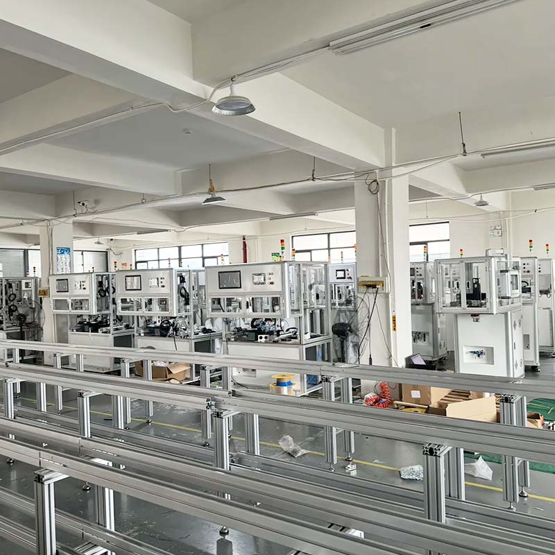
Automotive production typically requires systematic quality control throughout the process.
Inspection can include:
- Incoming material checks
- First-piece inspection
- In-process dimensional checks
- Gauge inspection
- Surface inspection
- Final dimensional verification
Depending on the component, measurement tools can include calipers, micrometers, height gauges, optical systems, CMM equipment, dedicated checking fixtures, and go/no-go gauges.
Dedicated fixtures are useful when several functional dimensions need to be verified rapidly during repeat production.
Measurement systems themselves must also remain controlled and calibrated.
First Article and Process Validation
Before production volume increases, manufacturers often validate early parts carefully.
The objective is to verify that:
- Tooling produces the intended geometry
- Material forms correctly
- Critical dimensions are stable
- Inspection methods are suitable
- Downstream assembly requirements are met
Tooling adjustments are easier to manage before the production process is fully released.
For automotive projects, customers may also define specific approval procedures and documentation requirements.
Suppliers should confirm these requirements before production instead of assuming one generic approval process is acceptable for every customer.
IATF 16949 and Automotive Supply Chains
Automotive manufacturing operates within demanding supplier-quality systems.
IATF 16949 was developed by the International Automotive Task Force to harmonize quality-management approaches across the global automotive supply chain.
For stamping suppliers, relevant customer expectations can involve areas such as process control, risk management, traceability, change management, supplier management, corrective action, and production consistency.
Requirements can also vary by direct customer.
The IATF publishes customer-specific requirements from automotive manufacturers, illustrating why suppliers need to understand both general automotive quality systems and the specific requirements of the company they supply.
A component supplier should therefore never assume that one generic quality document automatically satisfies every automotive customer.
Traceability
Traceability helps connect finished components with their production history.
Depending on customer requirements, records can include:
- Material lot
- Coil or heat number
- Production batch
- Tooling status
- Inspection results
- Process date
Traceability becomes valuable when investigating a later quality issue.
Instead of treating all historical production as identical, the manufacturer can identify which material or production batches may be involved.
The required level of traceability should be agreed before production begins.
Process Change Control
Changes that appear minor to a supplier may be significant to an automotive customer.
Potential changes include:
- Material supplier
- Material grade
- Tooling design
- Production equipment
- Manufacturing location
- Lubrication
- Secondary processing
- Inspection method
Automotive projects may require customer review or approval before some changes are implemented.
Suppliers should therefore maintain structured change control rather than modifying production informally.
Common Automotive Stamping Defects
Several recurring defects deserve attention.
Cracking
Cracking occurs when the material is stretched beyond its forming capability.
Possible causes include an inadequate bend radius, excessive draw depth, insufficient ductility, or unfavorable material orientation.
Wrinkling
Wrinkling occurs when sheet material is allowed to compress or flow uncontrollably during forming.
Blank-holder pressure and die geometry can influence this defect.
Springback
Springback causes the component to partially recover after forming pressure is removed.
This may change flange angles or overall geometry.
Burrs
Excessive burrs can result from tool wear or inappropriate die clearance.
Surface Damage
Scratches and tool marks can result from contaminated tooling, handling, or poor lubrication.
Dimensional Drift
Dimensions can gradually change because of tooling wear, feeder variation, material change, or press conditions.
In-process monitoring helps identify drift before significant quantities are affected.
Automotive Metal Stamping vs Sheet Metal Fabrication
Both processes manufacture sheet metal components, but they serve somewhat different production strategies.
| Factor | Automotive Stamping | Sheet Metal Fabrication |
|---|---|---|
| Tooling | Dedicated dies | Flexible cutting and bending tools |
| Repeat Production | Excellent | Good |
| Design Changes | Tool modification may be required | Usually easier |
| Cycle Time | Very fast after validation | More operation-dependent |
| Prototype Flexibility | Lower | Higher |
| High Volume | Strong advantage | Application dependent |
Sheet metal fabrication is often useful during development because design changes can be made without producing a complete stamping die.
Once the component geometry stabilizes and production volumes increase, stamping may become more efficient.
Some automotive programs therefore use fabrication for prototype components before transitioning to production stamping.
Automotive Metal Stamping vs CNC Machining
CNC machining removes material from solid stock, while stamping cuts and forms sheet.
Machining is suited to shafts, blocks, housings, precision interfaces, and complex solid components.
Stamping is generally more suitable for thin structural components, brackets, clips, panels, covers, and formed sheet parts.
Automotive systems use both technologies extensively.
The correct manufacturing strategy usually assigns each component to the process that best matches its geometry and functional requirements.
How to Choose an Automotive Metal Stamping Supplier
Supplier evaluation should go beyond the number or tonnage of stamping presses.
Automotive sourcing teams should examine tooling development, material experience, feeding equipment, press capability, quality systems, inspection resources, tool maintenance, automation, production capacity, and secondary manufacturing support.
Engineering communication is particularly important.
A capable supplier should be able to discuss:
- Material formability
- Springback
- Die clearance
- Strip layout
- Tool maintenance
- Critical tolerances
- Assembly interfaces
The objective is to identify manufacturing risks early rather than discovering them during volume production.
Information to Provide for an Automotive Stamping Project
Good technical information improves project evaluation.
Manufacturers generally benefit from receiving complete 2D drawings, 3D CAD data, material grade, thickness, critical tolerances, surface requirements, expected annual quantity, assembly requirements, inspection expectations, and required documentation.
Expected production volume is particularly important because it influences tooling strategy.
A component required in a limited engineering batch may use a very different production method from one expected to remain in repeat production for several years.
OEM and Custom Automotive Metal Stamping
Not every automotive metal component is a standard catalog item.
Vehicle manufacturers, equipment makers, aftermarket brands, and subsystem suppliers frequently require customized components based on their own drawings.
Custom automotive metal stamping allows tooling and production processes to be developed around those particular requirements.
Linametalworks supports OEM/ODM projects and describes its workflow as extending from tooling and prototype development into scalable mass production. Companies developing custom metal components can review its stamping capabilities or contact Linametalworks with drawings and production requirements.
Conclusion
Automotive metal stamping is a highly integrated manufacturing process used to produce repeatable brackets, reinforcements, clips, structural parts, electrical components, mounting elements, and other vehicle-related metal components.
Successful stamping depends on more than a powerful press. Material properties, die engineering, feeding accuracy, forming sequence, springback control, lubrication, tool maintenance, dimensional inspection, traceability, and downstream assembly requirements all affect production performance.
Automation improves the ability to coordinate feeding, positioning, punching, forming, and part handling, but stable tooling and sound engineering remain essential. This is particularly important in automotive manufacturing, where a small dimensional change can create problems later in robotic welding or automated assembly.
For OEM and industrial projects, the best stamping supplier is therefore not simply the company that can make the first sample. The more important capability is maintaining predictable quality throughout repeat production while supporting tooling, engineering changes, inspection, secondary processing, and long-term program requirements.
Linametalworks combines precision metal stamping with bending, machining, casting, forging, brazing, and broader custom manufacturing support for OEM metal components.
Frequently Asked Questions
What is automotive metal stamping?
Automotive metal stamping uses presses, dies, and material-feeding equipment to cut and form sheet metal into vehicle-related components. Processes can include blanking, piercing, bending, flanging, drawing, trimming, and multi-stage forming.
Which materials are commonly used for automotive metal stamping?
Common materials include low-carbon steel, high-strength steel, stainless steel, aluminum, and copper alloys. The correct choice depends on strength, weight, corrosion resistance, conductivity, formability, and component function.
What is progressive stamping in automotive manufacturing?
Progressive stamping moves coil material through multiple die stations while different operations are completed at each stage. Piercing, trimming, forming, bending, and final cutoff can therefore be incorporated into one continuous production sequence.
Why is springback important in automotive stamped parts?
Springback occurs when metal partially returns toward its original shape after forming pressure is removed. Excessive springback can change bend angles, flange positions, and assembly geometry, so tooling and process parameters must compensate for it.
What should buyers evaluate when selecting an automotive stamping supplier?
Buyers should evaluate tooling engineering, material knowledge, stamping and feeding equipment, process repeatability, quality systems, inspection capability, tool maintenance, automation, production capacity, traceability, and support for secondary manufacturing.